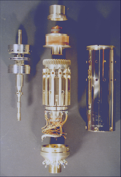
Liquid Helium Pump
Optimization of the Energy Efficiency of Helium Liquefaction Systems
For the operation of a helium liquefaction plant besides operational safety the most crucial figure of merrit is energy efficiency. For a long time energy efficiency has been optimized only for the liquefaction process, but not for the transfer of the liquid helium from the large storage vessel into the smaller transport containers. In a standard transfer process, the cold helium gas displaced in the transport container (typically about 15% of the total liquid transferred into the container) is just fed into the recovery system and getting warm. Moreover, the amount of liquid taken from the storage container has to be replaced by cold gas, leading to a strongly reduced liquefaction rate during the filling process. In total, about 30% of the liquefaction capacity is used up for the transfer losses.
The significant transfer losses can be avoided, if the cold gas is directly fed back into the storage vessel. At WMI this is realized by using a transfer line consisting of two concentric tubes placed inside a common vacuum insulation: in one tube the liquid helium is transferred to the transport containers and in the other the cold helium gas is flowing back into the storage vessel. In this way both the losses due to warming up the cold helium gas and the reduction of the liquefaction rate during the filling process are avoided. However, in this case a feed pump has to be used to transfer the helium liquid from the storage vessel into the transport containers. To implement this process, Robert Doll, Werner Wiedemann and Hartmut Berndt of WMI developed a submersible pump for liquid helium, which was taken into operation in 1988 (patent Nos. DE3715216A1, EP0289980A3, US4948348 (1988).
Using the submersible liquid helium pump developed at WMI, the transfer losses could be reduced from about 30% to 2%. Moreover, the time required for the filling process of the transport containers could be reduced by a factor of 4. At 100 revolutions per sec the pump achieves a transport capacity of about 15 liters/min, resulting in a filling time of less than 6 min for a 100 liter transport container .
A Submersible Pump for Liquid Helium
The WMI Solution
Because the storage vessels for liquid helium only have small openings for installing a pump, small dimensions at large pump capacity are key requirements. Furthermore, due to cumbersome installation in the storage vessel, one has to aim at a maintenance-free continuous operation. Moreover, due to the low latent heat of evaporation of liquid helium, the heat dissipated by the pump must be as small as possible. Finally, the appearance of vapor bubbles in the flow reduces the pressure and capacity achieved by the pump and must therefore be avoided. This makes a special kind of sealing of the entry and exit at the pump impeller and a special type of steam management necessary.
The optimum choice is a centrifugal pump using magnetic bearings for a fast-running shaft of a turbine rotor. For the technical implementation, special means for radial centering and axial positioning of the rotor have to be provided. The radial centering takes place via ring-shaped cutting pole shoes, which are placed at both ends of the shaft ends together with permanent magnets. The axial positioning of the shaft is achieved via actively-controlled magnet systems which act on disk-shaped pole shoes attached to the shaft. The control signal required for the steering of the axial magnets is obtained via optical sensing of the shaft position.
The submersible pump system developed at WMI provides a maintenance-free operation at low power dissipation due to the use of magnetic bearings in combination with a paddle wheel. Because the paddle wheel is realized as an integrative part of the magnetic bearing, a particularly simple structure is achieved. Moreover, it allows for a good sealing of the paddle wheel against entrance and exit of the pump system. For example, the flat surfaces at the top and bottom side of the closed paddle wheel can be directly used as pole faces for the axial magnet systems. The narrow gaps between the pole faces and the disk-covered paddle wheel act as seals of both the impeller entry and exit. Since the achievable axial positioning of the rotor is very precise, very tight choke gaps can be used, e.g. some 0.01 mm to 0.1 mm. At the same time, the requirements regarding radial positioning are quite low.
Patent:
A submersible pump, in particular for low-boiling liquids
Inventors: Robert Doll, Werner Wiedemann, Hartmut Berndt, DE3715216A1, EP0289980A3, US4948348 (1988).
Technical Description of the WMI Helium Pump
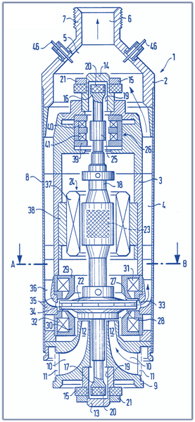
A vertical cross-section, a horizontal cross-section along the line A-B and a vertical cross-section of part of the pump systems is shown in the figures.
The submersible pump 1 has a housing 2, e.g. made of metal, with a preferably cylindrical shape. The inner housing wall 3 has axial grooves 4 being open to the outside. Upwards, these gooves 4 end into the housing space 5. The latter extends into an outlet 6, to which a pump line (not shown) can be connected via the connecting piece 7.
The housing 2 comprises a cover tube 8 in the region of the axial grooves 4, which closes the grooves 4 to the outside, so that they form axial channels. At the lower end of the housing 2, an end part 9 is attached, which forms several trumpet-shaped inlet channels 10. The inlet channels 10 extend from the ring-shaped side inlet opening 11 in curve-shaped manner upwards towards the outlet opening 12.
The end part 9 includes a copper liner 13. At the upper end of the housing 3, a similar liner 14 is attached. Each liner 13,14 carries an annular permanent magnet 15. The ends 16,17 of the rotor shaft 18 extend into the liners 13,14. There is considerable play between these ends and the inner wall 19 of the bearing bushings 13,14. To each shaft end 16,17 a cylinder-shaped permanent magnet 20 is attached. The magnetization direction of the ring-shaped permanent magnets 15 and cylinders 20 is axial and identically aligned.
The rotor shaft 18 carries a paddle wheel 22, a transversely magnetized permanent magnet 23 for the drive motor 24, and a ferrite core 25 for an inductive sensing device 26. The paddle wheel 22 has flat surfaces 27,28 on the top and bottom of its circumferential area. Pot magnets 29, 30, which are arranged above and below the impeller 22, interact with these surfaces. The coils 31,32 of the pot magnets cause attrative magnetic forces, acting via the plane pole faces 33,34 on the plane surfaces 27,28 of the impeller 22. The cylinder-shaped outer part of the ring-shaped pot magnets 29,30 form part of the housing 2.
The paddle wheel 22 is made of ferromagnetic material. Upon rotation of the impeller, the liquid to be pumped enters the impeller in axial direction through the inlet channels 10 and exits it radially. The paddle wheel 22 is surrounded by a fixed guide wheel (stator) 35, which is is inserted into the cover tube 8. Here, the wall 3 of the housing is free of axial grooves 4. The flow channels 36 of the stator 35 are curved upwards. They guide the liquid to be pumped upwards in the direction indicated by the arrow.
The position of the coil winding 37 is determined by that of the permanent magnet 23 of the drive motor 24. To avoid eddy current losses in the housing 3, it is enclosed with a ferrite ring 38. The coil winding 37 itself is sealed and fastened in a sealed manner inside the housing 3.
The ferrite core 25 of the sensing device 26, which is attached to the rotor shaft 18, is surrounded by a pot core 39, consisting of ferrite. It contains two coils 40,41. They are are part of the branches of a bridge circuit (not shown), which is operated at a carrier frequency of 30 kHz. If the ferrite core 25 is positioned symmetrical between the coils 40,41, the bridge is balanced and provides no signal. If there is some deviation from the central position, a signal is generated which is then rectified in a phase-sensitive manner, amplified and provided with a differential component in a suitable manner to the coils 31,32 .
The achievable positional accuracy of the impeller 22 is already in the range of the mechanical production tolerances of the impeller 22 itself, namely a few μm, so that gaps of a few 0.01 mm can be realized. This allows for a very good sealing of the liquid to be pumped between the inlet and outlet on the impeller 22. The pot magnets 29,30 together with the stator 35 form a compact unit with relatively short components, so that problems related to thermal expansion are avoided.
Low-boiling liquids are usually in equilibrium with their vapor. This entails that vapor bubbles are created wherever there is friction in the liquid due to rapidly moving parts. Gas bubbles in the liquid reduce the pressure generated by the impeller and the pump capacity and therefore should be avoided. This can be achieved by using a closed paddle wheel 22 (with base and cover plate) and by arranging holes 42 at a suitable positions. In this way, the bubbles generated on the rotor can get back into the liquid surrounding the submersible pump 1. These holes 42 perforate the housing wall 3 and the cover tube 8.
The housing 3 with the sensing device 26 and radial bearing is closed in upward direction. The liquid, which initially completely fills the submersible pump 1, is gradually evaporated when the pump is started by friction work of the rotor in the liquid. The resulting steam displaces the liquid from the interior, so that the rotor finally only rotates for the most part in steam, which leads to a reduction in friction losses. In order to make this effect even more efficient, at the lower end of the motor winding 37, a piece of pipe 43 with a funnel 44 is inserted. The funnel edge 45 extends close to the blade wheel 22. As a result, the liquid is kept away from the rotor up to the rotor wheel. The path of the steam, resp. steam and leakage flow, is indicated by arrows.
On the top of the housing 2, electrical feedthroughs 46 for the leads to the sensing device 26, of the motor winding 37, and the pot magnets 29,30 are placed. The electrical connections inside the pump housing are not shown.
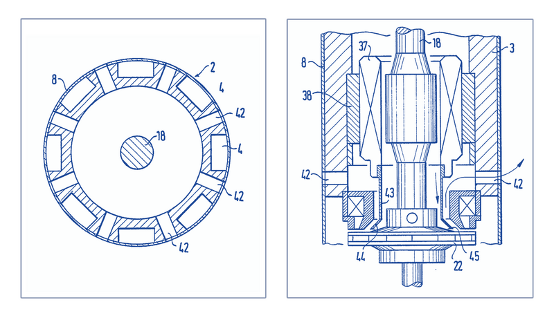
Right: Vertical cross-sectional view of part of the submersible pump (for explanation of the different parts, see text).