The WMI Helium Liquefaction Plant
A Long Tradition in Helium Liquefaction
The Walther-Meißner-Institute (WMI) operates a helium liquefaction plant since more than 60 years and supplies the two Munich universities and some other Munich research institutions with liquid helium. After Kamerlingh Onnes at Leiden (1908) and Mc Lennan at Toronto (1923), Walther Meißner was the third one worldwide who succeeded in liquefying helium in 1925 at Berlin. After moving to Munich in 1934 he continuously contributed to the improvement of helium liquefiers in collaboration with Linde AG.
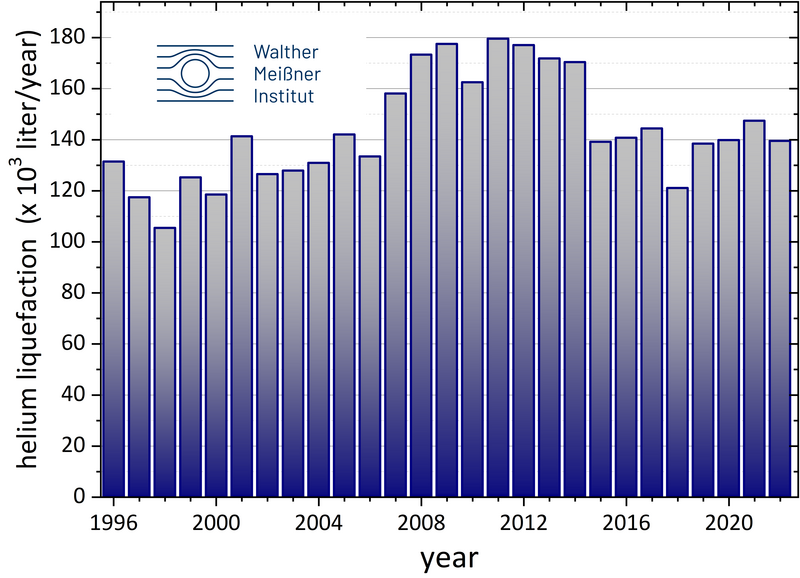
The reliable supply of liquid helium and efficient recovery of helium gas are key factors for internationally leading research locations. Over the last 30 years, WMI produced more than 140 000 liters of liquid helium per year on average (see figure) with a current market price of more than 2 Mio. €. The LHe consumption in the Munich area was changing over the past decades due to variations in research focus. For example, in the 1980s the LHe consumptions was strongly increasing after the foundation of the Walter Schottky Institute at TUM and presently is decreasing again mainly due to the improvement of cooling techniques (e.g. dry dilution refrigerators, magnetic cooling) which do no longer need liquid helium.
History of helium liquefiers operated at WMI
<1967 | WMI-built liquefiers, e.g. valve-less expansion machine after Doll and Eder. | |
1967-1981 | Linde helium liquefier, Linde AG, Germany. | |
1982-2003 | TCF 100 gas bearing turbine machine with ejector system, Sulzer AG, Switzerland | |
2004-2022 | TCF 20 gas bearing turbine machine with ejector system, Linde Kryotechnik AG, Switzerland | |
since 2022 | VL 100 gas bearing turbine machine with ejector systems, Vorbuchner GmbH & Co. KG, Germany |
Submersible pump for liquid helium
Since 1988, the liquid helium is transferred from the 5.000-liter liquid helium storage vessel into the transport containers delivered to the customers by a liquid helium transfer pump developed by Doll, Wiedemann and Berndt of WMI (patent Nos. DE3715216A1, EP0289980A3, US4948348 (1988). This approach considerably increased the efficiency of the helium liquefaction systems, as flash gas losses during the transfer of liquid helium between the storage vessel and the mobile transport containers are strongly reduced. At the same time, a liquefier with an ejector system is required to liquefy into an unpressurized liquefier tank.
« read more »
Helium liquefaction team & Informations for LHe Users
The WMI helium liquefaction plant is operated by a team of three experienced technicians headed by a cryo engineer.
« read more »
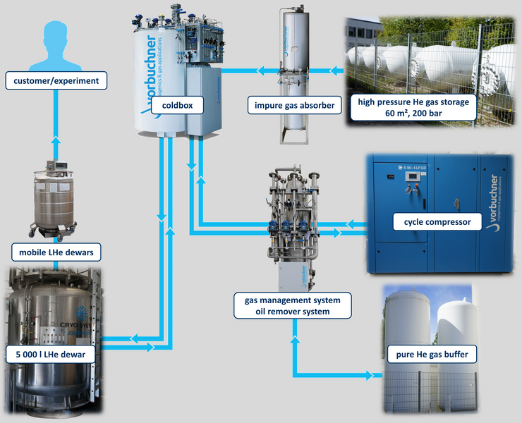
The Present Liquefaction Plant Based on a VL 100 Liquefier
At present, the WMI helium liquefaction plant is based on the VL 100 helium liquefier from Vorbuchner GmbH. The VL 100 liquefier is a fully automated, processor-controlled helium liquefaction system with a screw compressor, gas-bearing expansion turbines and an integrated freezing-purifier for processing contaminated helium (He) as the main components.
Principle of Operation
For the cooling of the helium gas a Claude process is used. In this method the compressed gas is doing mechanical work at the expense of its kinetic energy and thereby cooling down. To liquefy the gas this principle is combined with a Joule-Thomson expansion.
Compression: A screw compressor compresses the purified helium gas from 1.05 to about 12.5 bar, constantly dissipating the resulting compression heat. Traces of oil in the circulating gas are removed by coalescer filters and a special oil absorber.
Expansion: The cooling of the gas is achieved via two dynamic gas-bearing expansion turbines connected in series. In stationary operation, the final temperature after the second turbine is about 12 K. At temperatures below 8 K, part of the circulating gas is expanded to ≈1 bar by a Joule-Thomson valve (JT) and an ejector system. This produces partly liquid helium with a temperature of ≈4.2 K. In the transfer line, the 4.2 K cold helium is transported from the cold box of the liquefier to the 5.000-liter liquid helium storage vessel.
Performance Data
The VL 100 liquefier system is optimized for helium liquefaction using LN2 precooling. Despite the achievable liquefaction rate the energy consumed per liter of liquefied helium is of key importance as energy costs represent the key cost factor in helium liquefaction.
without LN2 precooling | with LN2 precooling | |
liquefaction rate (l/h) | 26.2 | 79.9 |
power consumption (kW/liter LHe) | 3.29 | 1.18 |
Heat Exchangers
The cold helium gas generated in the expansion process is used together with the low-pressure flow from the turbines to precool the warm gas in a counterflow principle using aluminum plate fin heat exchangers.
Freezing purifier
Since air, moisture and other impurities in the recovered helium gas form frozen deposits during cool-down, they have to be removed efficiently. The VL 100 helium liquefier uses integrated cleaning lines inside the coldbox based on cold surfaces generated by the process gas. The contaminated helium can be cooled down to ≈30 K in order to remove contaminations by freeze-out.
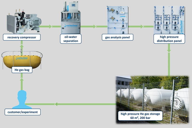
Helium Recovery System
Since helium gas, which has escaped to the ambient atmosphere, can no longer be recovered, WMI does not only operate a helium liquefier, but also a complex recovery system together with the Munich universities. The helium gas is recovered at the various experimental facilities/buildings of LMU, TUM and MPQ and fed back into the liquefaction process at WMI. On the Garching Research Campus, this is realized by underground tubes. Overall, a recovery rate of about 90% is achieved, providing safe helium supply and significant independence of the fluctuating helium market.
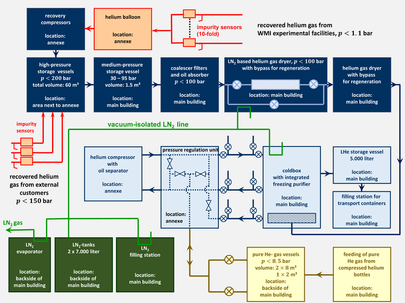
WMI itself also operates a helium recovery system with a recovery rate of about 95%. It consists of the following components:
- Helium balloons: Helium gas from the experiments is stored in two 10 m3 helium balloons equipped with a non-contact level measurement, avoiding balloon stressing and enabling longer compressor run times.
- Compressors and high-pressure storage: WMI operates 3 Sauer & Sohn helium compressors with a capacity ranging between 25 and 80 m3/h. The master compressor is determined on the basis of the running hours in order to distribute the run time equally among redundant compressors. The helium gas is compressed into five high-pressure cylinders with a total storage volume of 62.5 m3 and storage pressure of up to 200 bar. The distribution of the gas into the different cylinders is realized via a high-pressure panel.
Impurity analysis
Contamination of the helium gas with air, oil and other impurities are reducing the efficiency of the liquefaction process. Therefore, the quality of the helium gas must be monitored continuously. In the worst case, contaminated gas can be fed into a quarantine bundle. To increase the uptime of the system, contaminations are quickly detected and reduced to a level preventing failures of the freezing purifier.
Gas purifying systems
Since air, moisture, oil vapor and other impurities in the recovered helium gas form frozen deposits during cool-down, they have to be removed efficiently. Therefore, the WMI helium liquefaction plant uses several systems for purifying the helium gas (oil-water separator, coalescer filters, LN2 based gas dryer, freezing purifier).
Safety measures
To avoid losses of helium gas both in the low and the high-pressure part of the recovery systems, all relevant pipes are equipped with gas meters. In this way, leaks can be detected immediately. In particular, the rotating compressors can also be continuously monitored.